

IRIS Dampers
Description
IRIS dampers are a brilliantly simple solution for fast and exact measurement, balance and control of airflow. They are ideal for supply and exhaust tracking control, individual comfort control, and any space requiring accurate airflow regulation. For example, office buildings, pharmaceuticals, clean room environments, and laboratories are applications suitable for IRIS dampers. Its unique design allows for airflow to be measured and controlled at a single station. As a result, it saves time and money in initial installation and commissioning, and those applications requiring air balance on a regular basis.
IRIS dampers are comprised of a casing, damper blades, an adjustment or regulating nut, an airflow adjustment chart, and airflow taps. Blades and casing are manufactured from galvanized steel or 316 stainless steel (IRIS-S). The remaining components are made from high strength plastics and rubber.
Features & Benefits of IRIS Dampers
- Precise airflow measurement
- Accurate air balancing to +/- 5% in a straight duct
- Single station measurement and control
- Reduced field labor time
- Hot dipped galvanized steel construction
- Fitted EPDM gasket for airtight mounting
- Compact design, superior performance
- Fully retractable blades for duct cleaning
- Max operating temperature:
- 180 F continuous
- 250 F intermittent
- Available in ten sizes: 4″ through 32″ diameter
- Capacities: 15 cfm to 20,000 cfm
Positive Seal Construction (Optional)
Some applications may require a fully closed damper. For those requiring a 100% shutoff, a positive seal option is available on sizes 4″ through 12″, in both galvanized and stainless steel IRIS dampers.
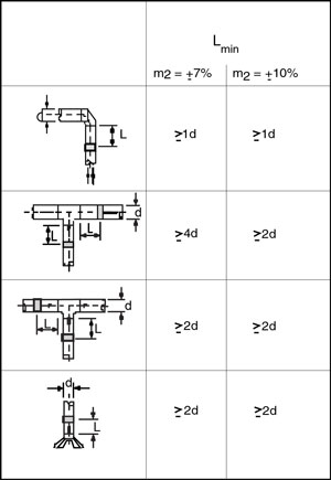
Figure 1
Recommended Installations
The calibration accuracy of an IRIS damper during disturbance free airflow is 5%. However, when an IRIS damper is installed near duct fittings, measurement accuracy may be affected. For optimum operation and airflow control, the chart (Figure 1) indicates the recommended distances between an IRIS damper and duct elbows, tees and transitions. From the chart, to achieve the airflow accuracy, m2, distance Lmin defines the minimum distance separating an IRIS damper from the fitting.
Selection
Airflow, pressure drop, and sound requirements are the criteria to consider when applying an IRIS damper. The IRIS damper represents a resistance to airflow in a duct, as do the duct and fittings. Selecting an IRIS damper is simple. In the case of an existing duct, choose an IRIS damper to match the duct size.
Alternatively, use the IRIS damper selection curves on pages 4 & 5 of the PDF Brochure. Select an IRIS damper at a mid-range setting to match desired airflow and pressure drop. This establishes the required duct size. Additionally, this provides the end user with balancing flexibility in the event that airflow requirements should change.
Consideration of the total pressure drop and sound requirements at design airflow is important. The selection curves indicate the total pressure drop of an IRIS damper at a given airflow and damper position.
Additionally, sound pressure cures across various damper settings are provided. LA is the sound pressure level with 4 dB room attenuation.
Visit CFM Select to utilize Continental Fan’s state-of-the-art fan selection and quotation platform.
Airflow Control and Balance
Once an IRIS damper has been installed and the system is operational, the damper may be adjusted to deliver required airflow using the airflow adjustment chart located on the damper. Airflow Adjustment Charts for IRIS and IRIS-S dampers are shown on pages 6 & 7 of the PDF Brochure.
Each IRIS damper contains two airflow taps (pressure ports) and an Airflow Adjustment Chart. By connecting a pressure gauge to the taps of the damper, the pressure drop across the damper blades can be measured. The illustration (Figure 2) shows the setup for making a pressure measurement.
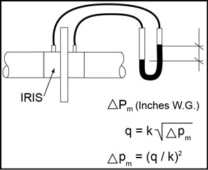
Figure 2
Each damper setting has a unique ‘k’ factor that defines the curves at different damper settings. The air velocity flowing through the orifice of the damper is proportional to the measured pressure drop. Once the velocity is known, the airflow can be easily calculated when the cross-sectional area of the orifice is known. The relationship between pressure drop and airflow through an IRIS damper is
q = k√(ΔPm)
q = airflow (cfm)
ΔPm = measured pressure drop (in. w.g.)
k = constant of proportionality (dependent upon orifice area)
For initial airflow balance, note the damper position and related pressure drop. Refer to the Airflow Adjustment Charts to determine the airflow.
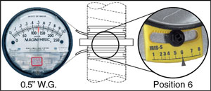
Figure 3
To adjust to a new airflow, locate the desired airflow on the Airflow Adjustment Chart and adjust the damper position until the required pressure drop is achieved (Figure 3).
Applications for IRIS Dampers
- Office buildings
- Pharmaceuticals
- Clean room environments
- Laboratories
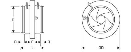
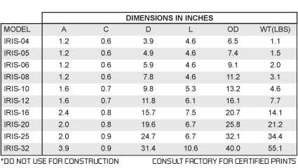
Fan Dimensions
- Select Charts / Diagrams tab below
To learn more about IRIS Dampers, read our Technical Article on IRIS dampers.

1967 Wehrle Drive, Suite 3
Buffalo, New York 14221
10212 Freight Drive
Dayton, Ohio 45377
12-205 Matheson Boulevard East
Mississauga, Ontario L4Z 3E3
1-800-779-4021 | info@continentalfan.com
