Products
EC Fan Array Application Guide
Description
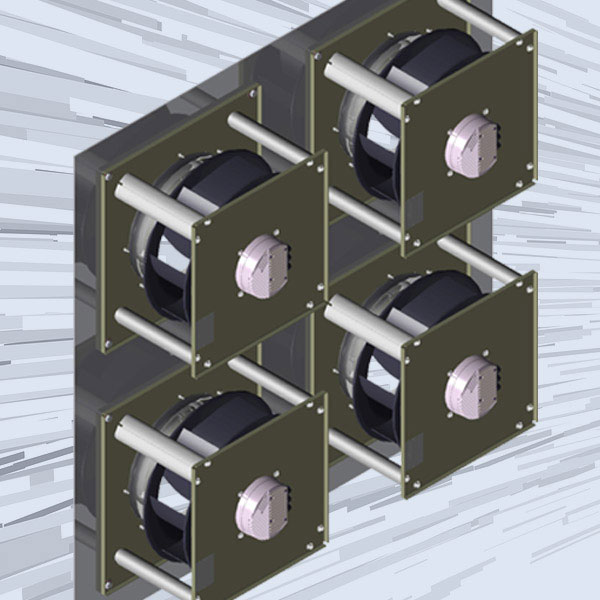
What is an EC Fan Array?
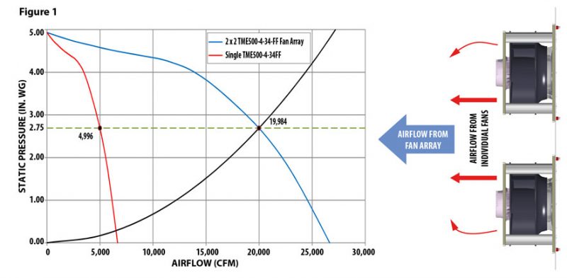
An EC Fan Array is a wall of EC motorized impellers that operate in parallel. When identical fans operate in parallel, the total airflow rate of the system is the product of an individual fan’s airflow rate times the number of fans in the array. For example, consider a system with a design point of 20,000 cfm at 2.75 in. wg. One TME500-4-34FF EC motorized impeller moves approximately 5,000 cfm at that pressure. Thus, a 2 x 2 fan array would be able to achieve approximately 20,000 cfm. This is illustrated in Figure 1.
Design
There are a few key principles to keep in mind when designing a fan array.
The spacing of the fans in the array is important. Studies have shown that when the ratio of the sides of the array to the number of fans and impeller diameter is greater than or equal to 1.55, there is no loss of performance.
This equation can be expressed as: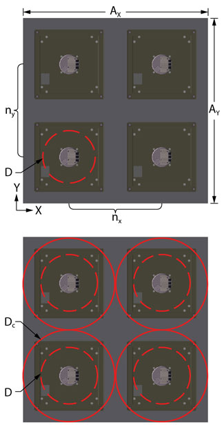
A ⁄ (n×D) ≥ 1.55,
A – length of array in x or y plane
n – number of fans in x or y plane
D – outside diameter of fan)
Alternatively stated, as long as the ratio of the width of the array to the product of the number of fans in a row and the diameter of the impeller is not less than 1.55, then performance would not suffer. (The same ratio holds true if using the height of an array and the number of fans in a column). That is because the ≥ 1.55 ratio provides enough space around the impeller for the airflow to fully develop.
To prove this, assume a fan array is square, having sides equal to length A. Starting from the diameter of a circle circumscribed around a rectangle, and applying it to a square section:
Dc = (a² + b²)½
Dc = (2A²)½
Using the above with A = 1.55D:
Dc = [2(1.55D)²]½ = (4.805D²)½
Dc = 2.19D
This means that each fan operates in its own circular area of 2.19D. Thus, the ≥ 1.55 ratio places more than a full diameter between any two adjacent fans and helps negate any system effect that would otherwise occur.
If this minimum ratio is maintained, there is no need for partitions between the fans in a fan array. In fact, there would be a slight loss due to friction when a fan array has partitions. Partitions may help provide structural integrity, but they are not required to improve air performance.
Sound
The more fans there are, the more noise, right? Although this may be a true statement, one needs to understand what is being compared.
The approximate increase in noise is calculated by:
L = 10 log(n),
L – increase in noise (dBA)
n – number of fans)
This means a fan array with 9 impellers would result in roughly a 10 dBA increase as opposed to running a single large fan.
A 10 dBA increase is perceived by the ears to be twice as loud as the reference. If an individual fan emits 75 dBA, then a fan array containing 8 more units would emit 85 dBA. Although this value still seems high, it is important to understand this should be compared to 90-95 dBA of an equivalent single large fan system. In addition, the good news with a fan array is that smaller impellers emit noise in higher frequency bands, making it easier to attenuate.
EC Fan Array Operation & Control
EC Motorized centrifugal impellers with integrated controls are ideally suited for fan arrays, and can be provided with closed loop control for constant pressure, or constant airflow applications.
Constant Pressure Applications
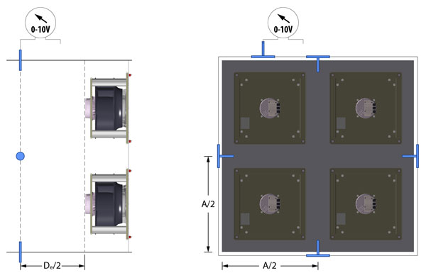
In order to provide constant pressure in a supply air ventilation system, a pressure transducer, typically with a 0-10V output, should be applied to average the static pressure around the fan discharge. Using a length of A for each side of a square duct, and the equation for equivalent duct diameter from earlier, static pressure taps should be installed in the center of each side (i.e. A/2) and one half of an equivalent duct diameter downstream of the fans (i.e. De/2).
Constant Airflow Applications
In order to provide constant airflow, the differential pressure upstream of the fan and at the inlet cone must be determined, and then used as the set point on a pressure transducer. There are two ways to determine the differential pressure required: through experimentation (recommended, by adjusting speed of fans until desired airflow is reached), or through calculation. If calculated, the differential pressure is:
Δp = 0.00298ρ(Q/k)²,
Δp – differential pressure (in. wg)
ρ – density (lb/ft³ )
Q – airflow rate (cfm)
k – calibration factor (ft²s / min)
When dampers in the system close, reducing the airflow, the differential pressure will decrease. Once it decreases below the set point on the transducer, the feedback of the control will force the fans to increase their speed, so that the airflow returns to the original volume flow rate. This is illustrated in Figure 2.
Redundancy
Due to its inherent construction, a fan array creates redundancy when properly designed.
For example, assume the required operating point for a ventilation system is 15,000 cfm at 2.75 in. wg. A 2 x 2 fan array consisting of (4) TME500-4-34FF operating at 1595 rpm can achieve this performance (solid blue line). Should one of the four fans operating at 1595 rpm fail, the remaining three fans would increase to their maximum 1800 rpm speed to compensate for the loss (solid red line). This is illustrated in Figure 3.

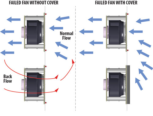
An individual fan that has stopped working should have the inlet covered to prevent backflow, until the issue can be resolved. Should the need arise, a similar fan can easily be removed and transported.
Whether a company’s maintenance crew or a contractor is responsible for a fan array, less time and resources are required for planning and implementation. This means less heavy equipment required and less downtime experienced. Production loss is mitigated. All of these factors reduce the expense of maintaining a fan array.
Why Choose an EC Fan Array?
There are a multitude of problems that can arise when a fan fails. One of the biggest concerns is downtime, resulting in lost production and revenue. There is 0% chance of immediate recovery when a single large fan system fails. Depending on the failure, it could be days, if not weeks or months, to get a fan running again. The costs could be rather significant.
In addition, as a business grows, so does its infrastructure. As walls and other obstructions go up, moving and/or replacing a single large fan system could become extremely challenging. Will the fan fit through those doors? How to negotiate those tight corners, much less the narrow hallways? How much does the fan weigh? What’s the cost for a crane rental? What’s the lead time for replacement parts? Should we look at a complete new unit?
Whether you are in the market for air handlers, a load bank, or looking at a retrofit project, a fan array may be worth considering.
If you would like a PDF copy of the above information, please submit a request.
-
Applications
- Air Handlers
- Load Banks
- Cabinet Cooling
- Retrofit Projects

1967 Wehrle Drive, Suite 3
Buffalo, New York 14221
10212 Freight Drive
Dayton, Ohio 45377
12-205 Matheson Boulevard East
Mississauga, Ontario L4Z 3E3
1-800-779-4021 | info@continentalfan.com

