Dampers are commonly used in HVAC applications to regulate airflow within a duct or other air-handling equipment. Applications, efficiencies, power consumption, maintenance costs, and their effect on airflow vary widely.
Conventional dampers typically comprise a valve, blade or plate in a frame. They are available in various types, shapes and sizes, ranging from small round butterfly backdraft dampers to large rectangular parallel blade designs.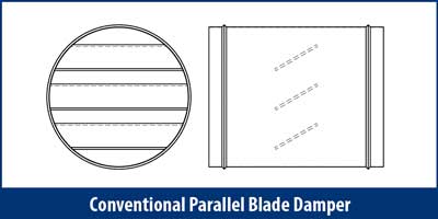 In any HVAC system, it is important to be able to measure, balance and control airflow. This is normally accomplished by varying the damper blade(s) position and altering the airflow resistance of the system.
IRIS dampers are a brilliantly simple solution for fast and exact measurement, balance and control of airflow. Their unique design is an ingenious application of the orifice plate principles in fluid dynamics, and allows for airflow to be regulated quickly and accurately at a single station.
This distinct IRIS damper feature saves time and money in initial installation, set-up and follow-up commissioning. It is ideal for any space requiring accurate airflow regulation, supply and exhaust tracking control, individual comfort control, or applications that require air balancing on a regular basis.
An IRIS damper comprises a casing, interlocking damper blades, a blade setting chart with an adjustment nut, airflow measurement pressure taps and an airflow adjustment chart. 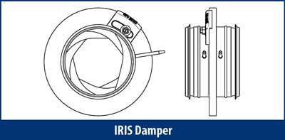 The interlocking blades create an adjustable aperture that regulates air flowing through the damper. This aperture can be adjusted from the outer perimeter of the damper utilizing a blade setting adjustment nut and an integral blade setting chart.
Airflow can be measured quickly, and air balancing performed easily and accurately using the built-in pressure taps located in the outer ring of the damper.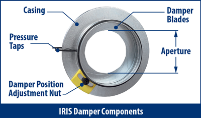
ADVANTAGES
IRIS dampers possess a number of distinct advantages over conventional volume control dampers:
Precise Airflow Control
- Precise airflow control and measurement, with an accuracy of up to ± 5%, is possible in a straight duct run with a properly installed IRIS damper.
- Ideal for applications that require very precise airflow control, measurement and balancing. Clean rooms and laboratories are but two examples.
Single Station Measurement
- Built-in pressure taps allow for accurate pressure drop readings across the damper, and provide a single station for measurement, control and balancing.
- Single station operation results in reduced field labor time and cost savings.
Fully Retractable Blades
- It is possible to fully retract the blades of an IRIS damper, resulting in a completely open duct.
- When fully retracted, there is nothing obstructing the airway therefore resulting in a zero local pressure drop.
- Fully retractable blades allow for easy cleaning of a duct.
- A fully open IRIS damper results in a lower pressure drop than any conventional damper.
Better Airflow Characteristics
- Perhaps the biggest single advantage to using an IRIS damper comes from its airflow characteristics.
- Conventional dampers using parallel blades direct airflow to the walls of the duct, thereby creating significant turbulence and leading to reduced efficiency and increased noise.
- With an IRIS damper, there is a uniform reduction of the cross-sectional aperture as the blades are closed. The airflow remains in the center of the duct and evenly distributed.
- Efficiency is improved.
- Noise level remains low.
Lower Noise
- A lower noise level may reduce or eliminate the need for costly sound attenuation.
Assorted Sizes
- Available in a broad range of sizes for a variety of airflow measurement requirements.
CONSTRUCTION BENEFITS
- Compact design, superior performance
- Available in an assortment of sizes for a broad range of airflow measurement requirements
- Hot dipped galvanized steel construction
- Fitted EPDM gasket for airtight mounting
- Capacities: 15 cfm to 20,000 cfm
- Max operating temperature:
o 180 F continuous
o 250 F intermittent
OPTIONS
POSITIVE SEAL (OPTIONAL)
Due to the interlocking blade design, standard IRIS dampers cannot close completely. A 100% shutoff, positive seal option is available for those applications that require a fully closed damper. A positive seal pod is positioned at the center of the IRIS damper. The closed damper blades converge on the center pod and allow for 100% shut-off capability.
SELECTION
Selecting the correct IRIS damper to use is quite simple. The criteria that need to be considered are airflow, pressure drop and sound requirement.
In the case of an existing installation, it is as straightforward as choosing an IRIS damper to match the duct size.
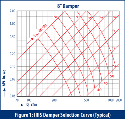
For new installations, IRIS Damper Selection Curves should be used (Figure 1). These curves indicate the Total Pressure drop across an IRIS damper at a given airflow and damper position. Sound pressure values across various damper settings are also provided.
An IRIS damper size should be chosen such that the desired range of airflow falls within the damper’s performance curve. Select a mid-range setting on the curve. This not only establishes the required duct size, but also provides the user with balancing flexibility should airflow requirements change.
Selection curves are available on pages 4 & 5 of IRIS Damper Application Guide.
INSTALLATION
An IRIS damper will deliver an airflow measurement with an accuracy of ± 5% when installed in a section of straight duct. Duct features such as elbows, T-junctions or diffusers tend to create disturbances in the airflow, and will reduce the air balancing accuracy of an IRIS damper to ± 10%.
In order to obtain the most accurate readings, an IRIS damper should be installed at a sufficient distance from these elements.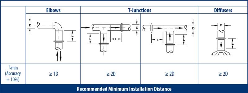
AIRFLOW CONTROL & BALANCING
Each IRIS damper has two built-in airflow measurement pressure taps and an Airflow Adjustment Chart (Figure 2).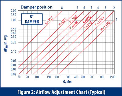 Once an IRIS damper has been installed in a duct and the system is operational, the initial operating conditions can be determined by simply connecting a pressure gauge to the two pressure taps, recording the measured pressure differential, (∆Pm), and noting the damper position (blade setting). The airflow can then be read off its associated Airflow Adjustment Chart.
To change airflow, locate the desired airflow amount on the Airflow Adjustment Chart and modify the damper position using the adjustment nut until the required pressure drop is achieved.
Air balancing can be achieved quickly and simply in the same manner.
Airflow Adjustment Charts are available on pages 6 & 7 of IRIS Damper Application Guide.
HOW IT WORKS
A fan running at a constant speed provides constant static pressure (SP) and airflow (cfm), which correlates to the resistance of the system it is operating in.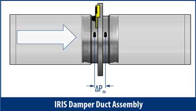 Opening or closing the IRIS damper blades will change its aperture and the total pressure drop across it (∆Pm), with a resulting change of airflow in the system.
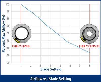 The airflow downstream of an IRIS damper is proportional to the measured pressure differential (∆Pm), and can be determined by using Equation (1) below:
Q = k4 √(∆Pm ) Equation (1)
Q = airflow (cfm)
k = constant of proportionality
ΔPm = measured damper pressure drop (in.wg)
In this equation, ‘k’ is dependent on the area of the aperture and unique to each IRIS damper and its damper position.
Based on Equation (1), Airflow Adjustment Charts (Figure 2) have been generated for all IRIS damper models. For each size, eight different damper position blade setting curves are provided (#8 represents the smallest aperture), along with their ‘k’ values. These charts are used for air balancing and determining precise airflow through the damper.
Note: The Airflow Adjustment Charts (Figure 2) differ from the IRIS Damper Selection Curves shown previously (Figure 1), and should not be used for selection purposes.
EXAMPLE
An upstream fan supplies air to a room at a constant flow and temperature through an 8” duct. In order to control the airflow to the room, an 8” IRIS damper is connected to the HVAC system in a long section of straight duct.
The damper position is initially set to 4. A pressure gauge connected to the pressure taps measures ‘ΔPm’ of 0.30 in. wg. Entering the Airflow Adjustment Chart (Figure 3) at 0.30 in. wg (A) and reading across to damper position 4 and then down, the airflow ‘Q’ can be determined to be approximately 340 cfm. The airflow can also be calculated by using Equation (1), where k4 equals 609:
Q = k4 √(∆Pm ) = 609 √(0.30) = 609 x 0.55 = 335 cfm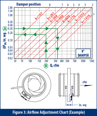 Let’s now assume that an airflow of 200 cfm is required for this application. To achieve the lesser flow, the orifice opening must be reduced by closing the damper blades. The new damper position can be determined by entering the Airflow Adjustment Chart at 200 cfm (B) and tracing a vertical line until it intersects with damper position 5, which represents a smaller aperture. By reading across horizontally, a ‘ΔPm’ of 0.18 in. wg can be seen. Finally, by confirming the pressure drop with a pressure gauge, the airflow, pressure drop and damper position can be recorded for future reference.
APPLICATIONS
IRIS dampers can be used in a wide array of HVAC systems, including office buildings, pharmaceuticals, clean rooms, laboratories, and any other applications where conventional dampers are typically used.
With the wide range of sizes and capacities available, IRIS dampers are suitable for most applications where accurate control of airflow is needed. They are especially suited for those that have strict performance and/or sound requirements. Compared to other types of dampers, IRIS dampers are quiet and ideal in applications where low sound levels are required.
Air balancing in HVAC systems is an important consideration. If proper balancing does not exist in buildings, inconsistent temperatures and poor air quality may result. IRIS dampers can be used to easily adjust airflow to different regions in a building, providing overall better air quality and resulting in improved comfort levels, increased energy efficiency, reduced maintenance costs, and a longer lifespan for HVAC equipment.
Optional positive seals can be added to the IRIS dampers and allow for airflow to be shut-off to certain areas when not required, resulting in further energy savings.
Laboratories, which require very precise air balancing and measurement, provide a good example of an application that can benefit from the use of IRIS dampers. In addition to being able to measure the exact airflow that is being delivered, it is important to have the ability to instantaneously change it to a new required amount at the same station without the need for additional measurement tools.
With optional stainless steel construction, IRIS dampers can also be used in corrosive locations.
Download a PDF copy of our IRIS Dampers Technical Article today!


